arrow_upward


Facilities

The main facilities are:
♦ 4 Physical Scale Laboratories:
Calm Water Towing Tank[ICTS-I3a-1].
Cavitation Tunnel[ICTS-I3a-2].
Ship Dynamics Laboratory[ICTS-I3a-3].
Models workshops[ICTS-I3a-4].
♦ 1 Field Laboratory for Maneuverability in open lake [ICTS-I3b].
♦ 1 Numerical modeling service for Numerical Hydrodynamics, CFD (Computational Fluid Dynamics) [ICTS-I3c].
These facilities are supplied with:
♦ Appropriate software for Computer Aid Design (CAD) for the design of models of ships and propulsion systems.
♦ Appropriate hardware for Computer Aid Manufacturing (CAM) for the manufacture of models of ships and propulsion systems.
♦ Resources for ship sea trials.
♦ Marine Hydrodynamics Consulting supported by more than 75 years of experience.
The main facilities are described below:
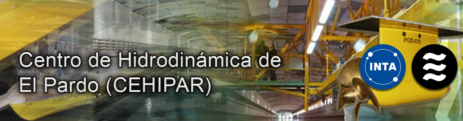
Calm Water Towing Tank (Physical Scale Laboratory ICTS-I3a-1)
The Calm Water Towing Tank is the facility where the hydrodynamic characteristics of ships and propellers without waves are studied.
Specifications
Basin
Towing carriage
Speeds up to 10 m/s.
Maximum acceleration 1 m/s².
Control software that automatically establishes the velocity profile of the tests.
Equipment
Among the wide variety of instrumentation available the following equipment should be mentioned:
Towing dynamometer.
Propeller dynamometer.
Dynamometers for propulsion tests.
Six-component dynamometer.
Video cameras and recording equipment.
Particle Image Velocimeter (PIV).
It also has a digital data acquisition system which collects model test data automatically and a computer program for the analysis and presentation of results, specifically developed for this facility. The modernization of this facility continues.


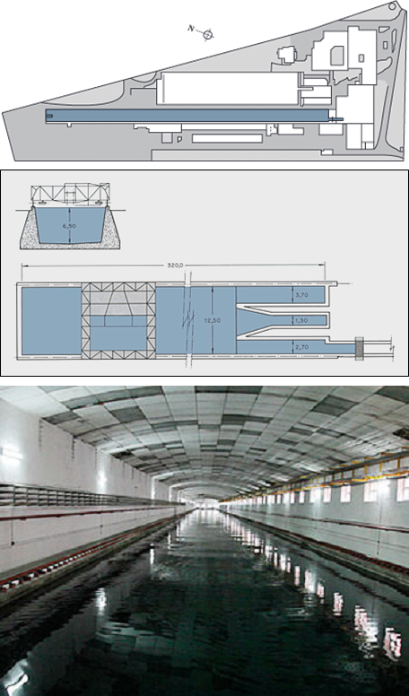
Cavitation Tunnel (Physical Scale Laboratory ICTS-I3a-2)
The Cavitation Tunnel is used to check and optimize propeller design by observing the cavitation inception and development, erosion risk, pressure fluctuations and noise generation. The tests can be performed with the propeller in free-stream, behind a screen simulating the ship wake, or introducing a dummy body (partial model of the ship hull). Non-conventional propulsion systems are also tested.
Specifications
Cavitation tunnel
Flow speed up to 11 m/s.
>Variable static pressure from 1.22 to 0.22 atm.
Cavitation number range between 0.32 and 130.
Propeller models diameter range 150 to 450 mm.
Wake flow simulation using wake screens and dummy models.
Equipment
The following equipment should be mentioned:
Non-intrusive speed measuring equipment with a two-component PDA laser-Doppler velocimeter.
Dynamometer for thrust, torque, vertical and horizontal forces and rate of revolutions.
Pressure transducers.
Measurement device for oxygen dissolved in the water.


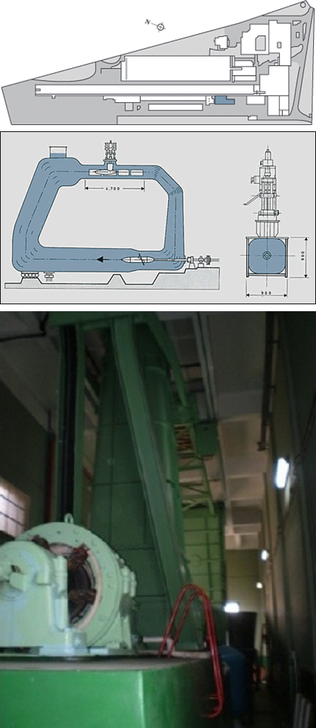
Ship Dynamics Laboratory (Physical Scale Laboratory ICTS-I3a-3)
The Ship Dynamics laboratory provides the latest technology for wave generation and test instruments and devices for measuring the movements of ships and other floating structures in the presence of waves and wind.
Specifications
Basin
Dimensions: 150 m long, 30 m wide and 5 m deep.
Not far from the wave generator the tank has a square (10x10) sectional pit of 5 m additional depth, thus achieving total depth of 10 m.
Wave generator
Sixty segments multiflap snake-effect generator with 60 segments. Its total width is 30 m and it has 60 articulated rigid flaps, with hinges located 2 m from the bottom of the channel. The segments or flaps that set up the wave generator are hydraulically operated independently. A wave absorber beach is mounted on the opposite side. This consists of stainless steel shavings, piled together to a thickness of 50 cm.
Types of waves generated:
Longitudinal and oblique regular waves of lengths between 1 and 15 m and heights up to 0.9 m. Oblique waves ±45º.
Long and short-crested irregular waves of significant heights up to 0.4 m.
Standard and arbitrary spectra.
Capacity to reproduce group spectra.
Episodic waves.
C.P.M.C. (Computerized Planar Motion Carriage)
The CPMC is a set of moving structures above the surface of the tank. It consists of a principal carriage and sub-carriages.
Its basic objective is high-precision reproduction of all possible horizontal movements of a ship or any floating structure at sea.
The principal carriage can be moved uniformly and horizontally along the tank. The three sub-carriages hang below the principle one and are mechanically independent and permit transverse, incremental and rotational motions that are superposed onto the movement of the principle carriage.
The transversal sub-carriage can vary the vertical position of the incremental and rotational sub-carriages, thus adjusting the conditions required for the tests.
The CPMC selfdeveloped software automatically controls the movements of the carriages, their positioning, the position of the model, acquisition of data, evaluation of the test runs, etc.
Equipment
The following equipment should be mentioned:
Instrumentation for the correct distribution of weights within the ship models and other seagoing structures, to reproduce the mass, inertia and position of center of gravity.
Krypton optical system for undisturbed measurement of the six motions of one or two models.
Dynamometers for up to 6 components of forces and moments on hulls.
Rudder dynamometer.
Propeller dynamometer for thrust and torque.
Wave height and relative motion probes.
Ultrasonic probe for high precision wave height.
Instrumentation for segmented models.
Underwater cameras.
Load cells.
Accelerometers.
Pressure transducers.


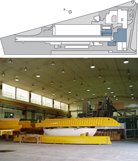
Model Workshops (Physical Scale Laboratory ICTS-I3a-4)
The models of ships, propellers and structures that are necessary for the tests are constructed in the workshops.
Specifications
Facilities
Central workshop for assembly of the models.
Mechanical workshop.
Carpenter workshops.
Workshop for propeller manufacturing.
Welding workshop.
Warehouse.
Cabin for fiberglass models construction in controlled conditions.
Painting room.
Equipment
Five-axes numerically controlled milling machine.
Model marking and quality control table.
Standard metal-working tools, such as lathes, milling and boring machines, etc.
tandard wood-working tools, such as saws, planers, etc.
Numerical control lathe.
Numerical control milling machine.
CAD/CAM of the models
Specific software is used for the design and manufacturing of model shape. The defined geometry is coded in machine language using industrial numerical standards.


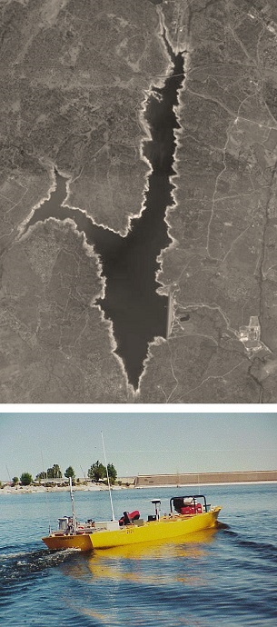
Maneuverability in open lake (Field Laboratory ICTS-I3b)
Maneuverability expresses the movements of the ship in a horizontal plane under calm water conditions. The maneuverability data is used for the design of the control surfaces, mainly the rudder. Variations of the control surfaces affect the course stability, the ability to run away in certain emergency situations, turning ability, turning radius for some kinds of fishing operations, the necessary stopping distance.
Free-running model maneuvering are done with a ship model, fitted out with the necessary instrumentation, tested in inshore waters. The model is guided by a remote control and is self-propelled and controlled. Valmayor reservoir, not far from Madrid and with enough water surface and depth for maneuvering without danger of collision, is used.
The organization has the knowledge, equipment and instrumentation necessary to perform and analyze free-running model maneuverability tests. The main maneuvers are: turning circle, pull-out, zig-zag, spiral and crash stop.
These maneuverability tests complement the maneuvers with captive model in which the model with its instrumentation is fixed through dynamometers to the computerized planar motion carriage (CPMC) of the Ship Dynamics Laboratory.


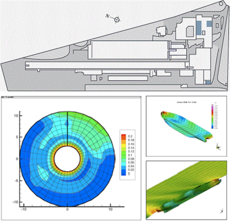
Numerical Hydrodynamics, CFD (Numerical Modeling ICTS-I3c)
The tools for mathematical computer-aided simulation, with Computational Fluid Dynamics (CFD) technics, are adapted for the optimization of hulls and propellers.
Specifications
Ship hulls
Commercial RANSE programs (ANSYS Fluent and CFX) are used for the study and modification of ship hull shapes. They are complemented with a large number of ancillary programs to linking these programs with the CAD/CAM systems.
The main results that can be obtained using these programs are: pressure and velocity fields on the hull and the water surface, wave distribution, wave profiles, streamlines, limiting streamlines, friction coefficient distribution, boundary layer thickness and lifting forces in lifting surfaces.
Propellers
TThe unsteady lifting surface method (VLM modality) is used to analyze the propeller hydrodynamic behavior. Alternatively, we can use a panel code for this purpose. The codes both calculate forces and sheet and tip-vortex cavitation, slipstream deformation and/or inclined shaft taken into consideration. They incorporate viscous corrections.
TThe main results that can be obtained using the propeller programs are: characteristic curves and efficiency of the propeller in open water conditions, thrust, power and efficiency of the propeller behind the ship hull for a given regime, six components of the vibratory forces and moments on every blade and the shaft, sheet cavitation development for chosen angular positions of a blade, volume velocity harmonics of the cavities, pressure distribution over the blades, Pressure fluctuations, due to the propeller, acting on the stern of the ship, and effective wake distribution.
Seakeeping
TPRECAL code is available for seakeeping calculations.


